Monday, February 28, 2022

Other BLOGS

 GeometricSparks is the fourth in a series of school mathematics blogs written for mathematics teachers and others in mathematics education. Each blog provides a commentary on 20 'weekly' sets of 5 'daily' tasks.


The first blog in the series is Algebradabra, with algebra tasks for secondary school students. The blog was later published in book form by the Association of Teachers of Mathematics (ATM).

 You can find the blog here,
and information about the book here.

A STUDENT version of Algebradabra, containing just the 100 tasks, without commentary, is available from DEXTER GRAPHICS

The second blog is Algeburble, with early algebra tasks for upper primary / lower secondary school students. The blog was also published in book form by ATM.


 You can find the blog here,
and information about the book here.


The third blog is MultipliXing, with multiplicative reasoning tasks for secondary school students. The blog is in the process of being published in book form by ATM.

You can find the blog here.

I have also produced a set of over 100 fractions task. These come as a set of SLIDES and a TEACHER'S GUIDE, both available as pdf files from DEXTER GRAPHICS


Monday, February 21, 2022

WEEK 20


6..4.1 Use the properties of a circle in constructions (1)
6..4.2 Use the properties of a rhombus in constructions (1)

This final set of tasks involves geometric constructions. Most require fairly standard techniques with ruler and compass, but some are mathematically quite challenging.

Monday: This is a fairly straightforward construction task, which can be solved in a variety of ways. The most obvious method, perhaps, but not the most efficient, is to construct a line through C perpendicular to AB and then construct another line through C perpendicular to that line.

A more efficient method, and perhaps mathematically more interesting, is to choose two points on AB (for example A itself and a point P) and to construct a point Q such that APQC is a parallelogram. A more efficient version of this is to choose P such that AP = AC, so that APQC is a rhombus. These two methods are shown below, left and below, right respectively.

Two versions of another method are shown below. These are mathematically interesting though not very efficient. The numbers show the order in which the construction was carried out. I leave it to the reader to discern the nature of each step!

Tuesday: This is similar to Monday's task, though in one way it is simpler: rather than some students coming up with the idea of constructing a parallelogram to produce the desired parallel line, we are told to construct a parallelogram, although this time there are three possible positions for the missing vertex.

Wednesday: It is possible to construct a copy of ABCD efficiently using a ruler, protractor and compasses, or a ruler and protractor only, or a ruler and compasses only.

Here is an efficient way of producing a copy, A'B'C'D', of ABCD using a ruler, protractor and compasses:
draw the 10 cm line segment A'B';
measure the internal angle at B and draw a line at that angle from B';
measure BC and mark a point C' on the line that distance from B';
draw an arc with radius AD, centre A';
draw an arc with radius CD, centre C';
mark the point D' where the two arcs meet and join D' to A' and C'.

Here is an efficient way of producing a copy, A'B'C'D', of ABCD using a ruler and protractor only:
draw the 10 cm line segment A'B';
measure the internal angle at B and draw a line at that angle from B';
measure BC and mark a point C' on the line that distance from B';
measure the internal angle at A and draw a line at that angle from AB';
measure AD and mark a point D' on the line that distance from A';
join D' to C'.

Here is an efficient way of producing a copy, A'B'C'D', of ABCD using a ruler and compasses only:
draw the 10 cm line segment A'B';
draw an arc with radius BC, centre B';
draw an arc with radius AC, centre A';
mark the point C' where the two arcs meet and join C' to B'.
draw an arc with radius AD, centre A';
draw an arc with radius CD, centre C';
mark the point D' where the two arcs meet and join D' to A' and C'.
 
Students might well come up with other variants of these methods, of which there are several. 

Thursday: The mirror line that is asked for here lies on the perpendicular bisector of AB. Students will probably know the standard way to construct this, but if not it provides quite a nice challenge.
The desired centre also lies on this line, but where exactly? (There are two possibilities here.)

Friday: This is a challenging task....

One way to solve this uses the idea of geometric enlargement:
Start by constructing (by any known method....) a line parallel to AB. Then, using a fixed compass, mark off 4 equally spaced points C, D, E and F, on that line. Draw a line through A and C and through B and F. Mark the point (G) where these two lines meet. Draw lines from G through D and from G through E, and mark the points (H and K) where these two lines meet AB. H and K cut AB into three equal parts. This construction is shown in the diagram below, left.
The diagram below, right is in some ways a simplified version, but involves the construction (by any known method....) of two parallel lines, in order to produce similar triangles.


Bonus: This bonus task has an elegant solution, but may require a flash of insight!


Sunday, February 20, 2022

WEEK 19


6..3.1 Understand and use translations (1)
6..3.2 Understand and use rotations (5)
6..3.3 Understand and use reflections (5)

6..3.4 Understand and use enlargements (2)

This is the final week of transformation tasks, mostly involving reflection and rotation. It can be thought of as a fairly demanding miscellaneous exercise.

Monday: The object being transformed (mapped) in this task is symmetrical, so we need to know the image of specific points to be able to determine the transformation.

In part i., we are told that vertex A is mapped onto vertex Y. The only single transformation that will do this, and map the whole blue rectangle onto the brown rectangle, is a rotation. This means B is mapped onto Z, C onto W and D onto X. How readily do students recognise that this is what happens?

A very grounded way of finding the centre of rotation here is to extend the blue line segment AB and the brown line segment YZ and to think about the corresponding points that this generates. The most significant pair of these occurs where the extended lines meet: since corresponding points coincide here, it must be the centre of rotation!

In part ii., we are told that vertex A is mapped onto vertex W. Again, the only single transformation that will do this, and map the whole blue rectangle onto the brown rectangle, is a rotation. This time B is mapped onto X, C onto Y and D onto Z.

It is an interesting challenge to try to find the centre using the grounded approach described for part i. However, it is not an efficient method for this task and is likely to involve several steps before corresponding points are found that coincide. An example of the method is shown below, where we can see that H (or H') is the centre.

Tuesday: It looks as though the transformation here is an enlargement, though we cannot be sure as none of the vertices of the object and image are grid points.
The construction lines drawn through corresponding points, shown in the diagram below, seem to meet at a single point, which suggests that the transformation is indeed an enlargement. An effective way to then find the scale factor is to compare the widths of the two shapes as the shapes seem to be a whole number of units wide, namely 2 and 7. This means the scale factor is 3½.

Wednesday: In this task we are shown only part of the image resulting from a transformation. From what we can see, the transformation could be a translation or a reflection.
A translation of 4 units across and 2 up will take E to E'. When this is applied to the rest of the plane, including G, then G' will have coordinates (1+4, 5+2), or (5, 7). The image of EFG under the translation is shown by the brown lines, below. 
 
If EF is reflected onto E'F', the mirror line will bisect and be perpendicular to the line segment EE'. The point on the mirror line closest to point G has coordinates (7, 8) and is 6 units across and 3 units up from G. So G' will have coordinates (7+6, 8+3), or (13, 11). The image of EFG under the reflection is shown by the heavy green lines, below.

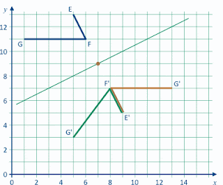
Thursday: In this task we are shown only part of the image resulting from a transformation. From what we can see, the transformation could be a rotation or a reflection.
A rotation of 180˚, with the centre at (7, 9) will map EF onto E'F'. The centre is 6 units across and 2 units down from G, so G' will have coordinates (7+6, 9–2), or (13, 7). We can also find G' by using the fact that F'G' will be horizontal (Why?) and G' will be 5 units from F'. The image of EFG under the rotation is shown by the brown lines, below. 
 
If EF is reflected onto E'F', the mirror line will bisect and be perpendicular to the line segment FF'. The point on the mirror line closest to point G has coordinates (3, 7) and is 2 units across and 4 units down from G. So G' will have coordinates (3+2, 7–4), or (5, 3). The image of EFG under the reflection is shown by the heavy green lines, below.

Friday: In this task we are shown only part of the image resulting from a transformation. From what we can see, the transformation could be a rotation or a reflection.
It may take a while for students to see that the centre of rotation that maps FE onto F'E' will be at (7, 5), even though this point is at the intersection of EF and E'F' produced. The line segments EF and E'F' are at 90˚ so the image of the horizontal segment FG will be vertical. This means G' will be 6 units above F' with coordinates (9, 6+5), or (9, 11). The image of EFG under the rotation is shown by the brown lines, below. 
 
If EF is reflected onto E'F', the mirror line will bisect and be perpendicular to the line segment FF'. The point on the mirror line closest to point G has coordinates (7, 5) and is 6 units across and 2 units down from G. So G' will have coordinates (7+6, 5–2), or (13, 3). The image of EFG under the reflection is shown by the heavy green lines, below.


Saturday, February 19, 2022

WEEK 18


6..3.2 Understand and use rotations (4)
6..3.3 Understand and use reflections (4)

6..3.4 Understand and use enlargements (1)

In this set of tasks, students are asked to complete a larger version of a wire shape that is placed in a different orientation. Thus the tasks could be said to involve rotation, reflection and enlargement, but without the need to find centres or mirror lines.

There are two broad strategies for solving the tasks, which might be termed local and global, and it is interesting to see which one the students favour.

Monday: In this task, a wire shape has been doubled in size, turned through 90˚ and flipped over. Thinking globally, we can, for example, say that each segment of the larger shape is perpendicular to the corresponding segment in the smaller shape. Thinking locally, we can, for example, say that end point A' and the other endpoint (which we might want to call F') are the same distance from B' and directly opposite. 

It might be helpful mentally to label every vertex of the shape, so that it can be referred to as ABCDEF. We have not done so on the diagram itself, to avoid obscuring the shape.

It can be useful to draw auxiliary lines. For example, it might help to extend AB to the other endpoint of the wire. Or one could enclose the given shape in a 'box', transform the box (rotating, enlarging, flipping) and then use local clues to 'fill' the box, as in the figure below.

Tuesday: Here the figure has been rotated through 135˚ and a line the length of the side of a grid square has become the length of the diagonal of a grid square (an enlargement with scale factor ×√2).

Students will probably be able to find the image of vertices D and E fairly easily. F might be more of a challenge: do students make use of the (global) fact that E'F' will be vertical, and/or the (local) fact that F' lies on A'B' produced?

Wednesday: Here the side of a unit square is mapped onto the diagonal of a 1 unit by 2 units square (an enlargement of ×√5). The images of vertical and horizontal lines are composed of such diagonals, but what about the image of the slanting segment EF?

Again, it is fairly easy to find the image of D and E. However, students (and the rest of us!) might have extreme difficulty predicting the length and orientation of E'F'. A simple way to locate F' is to use the fact that A', B and 'F lie on a straight line and that A'B' = B'F'. 

It is a nice challenge to compare the lengths of EF and E'F'. Is E'F' √5 times as long? It is also nice to find a way of confirming that angle D'E'F' is 45˚.

If we place our shapes onto the Cartesian plane, and image that, say, A and A' are both at the origin, as in the diagram below, then the original plane, as represented by the green grid lines, is transformed into the plane represented by the brown grid lines. Further, we can represent the transformation by the matrix shown beneath the diagram.
[Note: We are not suggesting that this treatment would work with students at Key Stage 3, but it might be of interest to, say, A Level students.]

We can take this further still, by breaking the transformation into two recognisable parts: a rotation of 116.6˚ anticlockwise [given that tan⁻¹(0.5) ≃ 26.6˚] and an enlargement with scale factor ×√5. In turn, these can be represented by the matrices below:

Thursday: A new and simpler shape, except that one of the segments, CD, is at a relatively strange angle - not horizontal, not vertical, not at 45˚. When CD is rotated through 45˚, what is its new orientation?!

Again, the image of the endpoint of the shape (D) is probably most easily located by relating it (locally) to the image of AB.

Having found the image of the whole shape, it is again a nice challenge to compare lengths and relate them to the scale factor, and to verify that angle BCD has been conserved. [It might again be useful to put the original shape inside a 'box' - in this case a 1-by-3 rectangle.]

Friday: Here we use Thursday's relatively simple shape again, but rotated through an obscure angle. The orientation of the image of CD may come as a surprise!


Friday, February 18, 2022

WEEK 17


6..3.2 Understand and use rotations (3)
6..3.3 Understand and use reflections (3)

This week's tasks involve reflection and rotation, but not of everyday objects; rather, the tasks are based on items from the CSMS Reflection and Rotation test that I developed.

Monday: This task looks rather unprepossessing, but it has proved to be quite challenging for some students. In part, this might be because students are rarely confronted with slanting mirror lines, other than the occasional line at 45˚ to the horizontal and vertical.

This task appeared on the CSMS Reflection and Rotation test, which was given to a representative sample of 449 Year 9 students back in the 1970s. Their responses, which were sketched freehand, were coded according to the scheme below. We devised some clearly defined rules for deciding whether, for example, a response was deemed to be correct or merely adequate. Of course, one could have come up with different rules. Suffice to say, about two-thirds of the sample (2% + 21% + 26% + 16% = 65%) had at least a fairly good sense of where the image should go and what kind of slope it would have. However, a sizeable minority of students (about one quarter of the sample) thought that the vertical flag's image would also be vertical, with some (10% of the sample) placing the image in roughly the right place (code 5) but others (14% of the sample) placing it horizontally (or vertically) across from the object (code 7).

Tuesday: In this task we ask students to assess a typical code 7 and code 5 response (see above). It is interesting to see whether students can identify the features captured by these codes and, if so, how they evaluate them.

Wednesday: This is another item from the CSMS Reflection and Rotation test. We found that 20% of the Year 9 sample answered this correctly, with roughly another 40% drawing the image with the correct slope but in the wrong position. It was rare for students to draw the image with one or other end-point in the correct position but with a wrong slope.

Thursday: This shows some responses to Wednesday's task. We found that it was quite common for students to place the image such that the base-points of the object and image were symmetrical about the centre of rotation, as in these three examples. Students who did this, usually drew an image with the correct slope (22% of the total sample), as in the case of Cleo and Dev, with a few (3% of the total sample) getting the slope wrong too, as with Eze.

Friday: This task is based on another item from the CSMS test. The original item was answered correctly by 14% of the Year 9 sample (using the criterion for 'correct' that we had devised), with another 25% giving a point roughly equidistant from the flags (like Hui, below) but not one that would give a 90˚ rotation. The point drawn by Gina, below, was particularly popular (21% of the sample) as was the 'symmetrical' point drawn by Flo (10%).


Note: It is interesting to consider the role that tracing paper can play in rotation tasks. Tracing paper could be useful in Task 17C for giving a sense of how the flag moves, although students would still need to determine where the movement stops. Its usefulness in 17E, say, to help locate a centre, is far less clear cut. It would provide an effective way of testing whether a chosen point is correct; however, it won't necessarily give useful feedback beyond that: if a chosen point turns out to be wrong, it can be difficult to see where an improved choice might be - so more a case of trial and error upon error than trial and improvement.

Extra: Here are two further tasks that might be interesting to try with students. They are designed to assess whether students have some sense of the idea that when an object is rotated through a given angle, the whole plane of which it is a part is rotated through that angle. In the case of the disc stuck to the wheel of a scooter (Task 17F), when the wheel turns through 90˚, so does the disc, even if we don't know its precise location. Similarly, if a piece of card is rotated (Task 17G) so that an arrow drawn on the card becomes horizontal, a second arrow on the card parallel to the first will also become horizontal.


Thursday, February 17, 2022

WEEK 16


6..3.3 Understand and use reflections (2)

This week's tasks mainly involve reflection, mostly of everyday objects, but they require fairly careful analysis.

Monday: This task could be said to involve enlargement as well as reflection. We can think of the drawing on the mirror's surface as an enlargement, scale factor ×0.5, of the image seen in the mirror, with the centre of enlargement at the viewer's eye. This means the drawing is the same size, regardless of the viewer's distance from the mirror (as long as they can reach the mirror to draw...).

You might want to try this, or a similar activity, in the classroom, if you can find a suitable reflective surface. Rather than a person's face, you could use a more easily measurable object placed next to the viewer's face, such as a book or a 30 cm ruler.

Tuesday: The clock shows half-past-two. Some students might over-compensate for the reflection and decide on half-past-three.

In 10 minutes' time, the clock will look something like this (note that the hour hand has moved slightly too, in the same direction as the minute hand):

Wednesday: The story in this task suggests that the word MATHS is written on the outside of the door. If that is the case, the word will look like mirror writing when viewed directly from inside the room, but not if it is viewed through some kind of mirror.

Thursday: This task takes quite a lot of coordinating! First, let us assume the bus is moving so smoothly it conveys no physical sensation of movement to Vera (if she shuts here eyes). Vera is facing forwards but the images she sees on here phone's screen seem to be receding into the distance in front of her, so it looks to her as if she is moving backwards at the same speed as the bus is moving forwards.

Things get more complicated if Vera can also see objects directly, out of the corner of her eye. These objects seem to be moving backwards at the same speed relative to Vera as she thinks she is moving. So if, say, her bus is moving forwards at 30 mph and her screen tells her she is moving backwards at 30 mph, then these objects would appear to be overtaking her by going backwards 30 mph faster. This might make sense if all she was seeing was stationary buses pointing the other way, or a line of railway carriages, but a bit unsettling if they were stationary objects like houses.

Friday: This is an example of the classic Heron's Problem. It is similar to task 08E but more general in that points A and B are not equally distant from the blue line.

Some students may feel intuitively that the desired point P will be towards the left-hand end of the segment of the blue line shown in the diagram. Others may well choose the midpoint of the segment. An elegant way of solving the task is to consider the shortest distance between point A and a point B', where B' is the reflection of B in the blue line.
 

Wednesday, February 16, 2022

WEEK 15


6..3.2 Understand and use rotations (2)

This week's tasks mainly involve rotation, again of everyday objects, but they require more careful analysis than last week's tasks.

Monday: This task shows a straightforward photograph of a small standard metal screw. A clockwise turn with a screwdriver will send such a screw further into the wood. It is possible to tell this from the direction of the screw's thread, though students might find it difficult to discern this and to explain how it works.

Tuesday: These photos are of the same screw as in Monday's task. If, say, we take that screw as our model we can construe it in several ways: for example, in an elevation view of the vertical screw, the screw's thread appears like a set of line segments that slope slightly downwards from right to left. This matches the threads of the screws in the middle three photos.
Alternatively, we could think of the screw as a (somewhat dangerous) helter-skelter: travelling down it, one would rotate in a clockwise direction when seen from above. Again, this would also apply to the helter-skelters in the middle three photos.

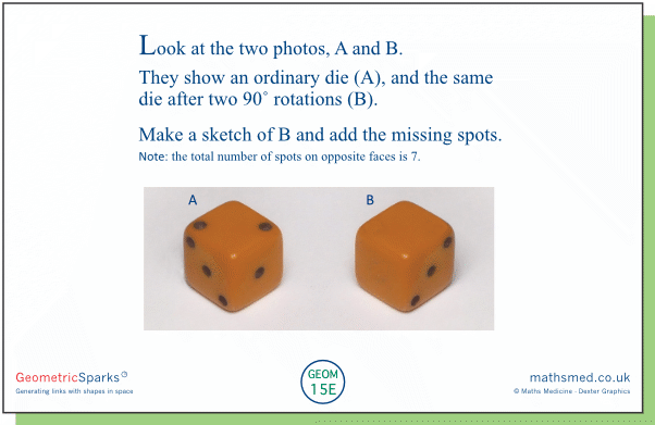
Wednesday: Here a particular 90˚ rotation is applied twice to a die. We can see from photos A and B that the rotation is about a vertical axis and in a clockwise direction when seen from above. When this is applied to the die in photo B, the right-hand vertical face showing 4 spots will become the left-hand vertical face, and will be replaced by the vertical face opposite the single spot. This will have 6 spots, since the total number of spots on opposite faces of an ordinary die is always 7. This solution is shown below the task.

Thursday: At first sight, it might look as though the die in photo A has not been rotated. It transpires that the rotation is about a horizontal axis perpendicular to the vertical face with 3 spots. As it is a 180˚ rotation, the faces with 2 spots and 1 spot are replaced by their opposite faces (5 spots and 6 spots, respectively). The solution is shown below the task.


Friday: This is quite a demanding task, with two solutions.

One way to get from the position in photo A to the position in B with two 90˚ rotations is this: rotate the die so that the face with 3 spots moves to the top and then moves to its position in B. The result is shown below, left. Another way is this: rotate the die about a vertical axis so that the face with 3 spots moves directly to the right, and then rotate about a horizontal axis so that the line of 3 spots slants the right way. If the second rotation is clockwise, we get the same result as before; if it is anticlockwise we get the result shown below, right.

It is likely that some students will imagine moving the die from A to B without breaking the move into single rotations. They can still get a solution by thinking about the faces that are neighbours to the face with 3 spots.